
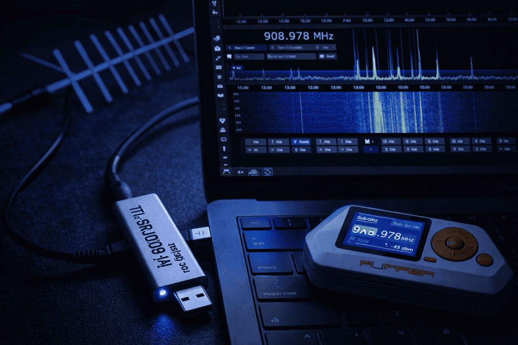
Your Flipper Zero caught a signal. Now what? You’ve got the raw capture file sitting on your device, but you can’t see what frequency hopping pattern it uses, whether there’s FSK or ASK modulation, or if there’s a preamble you’re missing. This is where most people hit a wall. The Flipper is brilliant for quick captures and replay attacks, but when you need actual signal intelligence, you need an RTL-SDR dongle and the right software setup. I spent three months testing different SDR workflows with the Flipper before finding a setup that actually works for real engagements.
The Flipper Zero’s CC1101 transceiver operates in the 300-928 MHz range with limited bandwidth visibility. You’re essentially listening through a keyhole. When I first started testing garage door openers for a client, I recorded what I thought was the full signal. Played it back. Nothing. Turned out the device used frequency hopping across 433.05 to 433.92 MHz, and the Flipper only captured one hop.
An RTL-SDR gives you the wide-angle view. The RTL-SDR Blog V4 covers 500 kHz to 1766 MHz with proper filtering and a temperature-compensated oscillator. You can watch the entire spectrum in real-time with SDR# or GQRX, spot patterns the Flipper can’t see, then use that intelligence to configure your Flipper captures properly.
The workflow I use now: RTL-SDR for reconnaissance and signal identification, Flipper for targeted capture and replay. They’re not competing tools. They’re complementary. The RTL-SDR shows you what’s happening across the spectrum, the Flipper lets you interact with specific signals you’ve identified. When you’re testing a building’s wireless access control system, you need both.
Here’s the critical difference: the CC1101 in the Flipper has about 812 kHz bandwidth. The RTL-SDR can monitor up to 2.56 MHz simultaneously with proper tuning. That matters when you’re dealing with modern rolling code systems that use spread spectrum techniques or when a target device transmits across multiple frequencies. I’ve tested alarm systems that send packets on three different frequencies within 200 milliseconds. The Flipper catches one. The SDR catches all three.
Getting the RTL-SDR working properly took me longer than it should have because most tutorials skip the driver issues. If you’re on Windows, you need Zadig to replace the default drivers with WinUSB drivers. On Linux, you need to blacklist the DVB-T TV tuner drivers that claim the device first. MacOS users have the easiest time, but you’ll still need to install librtlsdr through Homebrew.
For Windows, download SDR# (SDRSharp) from airspy.com. It’s the most stable option I’ve found for spectrum monitoring. Linux users should grab GQRX, which integrates better with the GNU Radio ecosystem if you want to build custom demodulation chains later. I keep both operating systems ready because some signal processing plugins only work on one platform.
Install Universal Radio Hacker (URH) regardless of your OS. This tool bridges the gap between raw IQ recordings and the signal files your Flipper understands. URH can decode ASK, FSK, PSK modulation schemes, perform automatic bit analysis, and export to .sub files that the Flipper reads natively. The first time I decoded a wireless doorbell signal in URH and pushed it to my Flipper, everything clicked.
Connect your RTL-SDR and launch SDR#. Set the RF Gain to about 25 dB initially. Too high and you’ll get intermodulation distortion from strong local signals. Too low and weak signals disappear into the noise floor. The RTL-SDR Blog V4 has three bias tee settings you can enable through software if you’re using an active antenna. For the Ultra-Wideband Log Periodic Antenna, you’ll want that bias tee enabled.
Calibrate your PPM correction. Tune to a known FM broadcast station, enable FM demodulation, and adjust the PPM slider until the frequency exactly matches the station’s published frequency. My RTL-SDR Blog V4 runs at minus 0.5 PPM, but every dongle is different. Write down your correction value and apply it every time. Frequency accuracy matters when you’re trying to replay a signal the Flipper captured at what it thought was 433.92 MHz but was actually 433.89 MHz.
Start with the entire 433 MHz ISM band visible. In SDR#, set your center frequency to 433.92 MHz and bandwidth to 2.4 MHz. You should see the noise floor as a relatively flat line across the bottom of the waterfall display. Any vertical spikes are signals. Press a car key fob or garage remote and watch what appears.
What you’re looking for: signal duration, repetition patterns, bandwidth, and modulation type. A typical car key fob transmits for 50-200 milliseconds. You’ll see it as a bright vertical line in the waterfall. Note the exact frequency. Right-click and set a bookmark. Modern remotes often transmit the same packet multiple times. Count the repetitions. That tells you how the receiver confirms valid signals versus interference.
Enable the frequency manager in SDR# and create a scanning list of common frequencies: 300 MHz, 310 MHz, 315 MHz, 330 MHz, 390 MHz, 418 MHz, 433.05-433.92 MHz, 868 MHz, 915 MHz. Hit scan and let it run while you trigger target devices. I found a building access system that transmitted on 868.3 MHz after scanning for fifteen minutes. The security assessment report listed it as 433 MHz because that’s what the Flipper was set to monitor.
Record IQ data when you see an interesting signal. In SDR#, click the gear icon, enable recording, and set it to baseband. Trigger your target device and record five seconds of spectrum. You now have raw IQ data you can replay in software, analyze offline, or process through demodulation chains without needing the physical device present. I keep a library of IQ recordings from every engagement organized by client and device type.
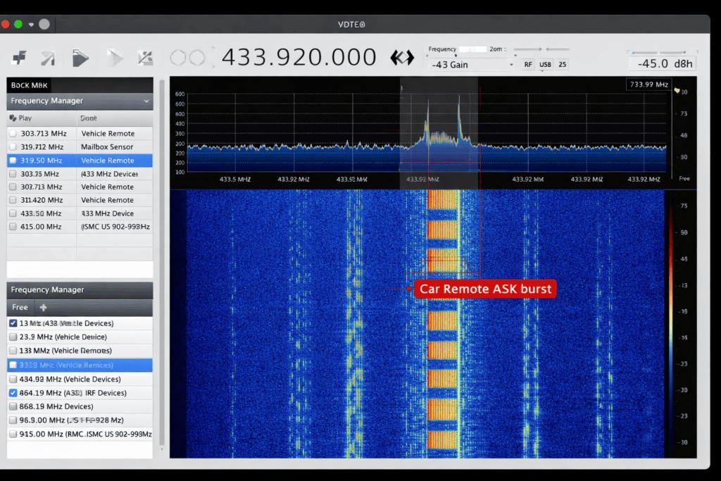
For actual demodulation, switch to URH. Load your IQ recording, and URH automatically attempts to detect modulation type. It’s surprisingly accurate. I’ve seen it correctly identify OOK (On-Off Keying, a form of ASK) on the first try for garage openers, FSK for tire pressure monitors, and even catch GFSK from Bluetooth Low Energy devices operating in the 2.4 GHz range when using a proper upconverter.
The analysis tab in URH shows you the decoded bits. Look for repeating patterns. Most wireless devices send a preamble (usually alternating 1s and 0s) followed by the actual data payload. Rolling code systems change part of the payload every transmission. Fixed code systems, which you should never find in production but somehow still do, send identical bit patterns every time. Document everything. Your report needs this level of detail.
Here’s where it gets practical. You’ve identified a signal at 868.35 MHz using your RTL-SDR. You know it’s ASK modulated, transmits for 120 milliseconds, and repeats three times with 50ms gaps. Now configure your Flipper to capture it properly. Go to Sub-GHz, Read, set frequency to 868.35 MHz, and set modulation to AM650 (the Flipper’s ASK setting).
The frequency matters more than people think. I watched someone try to replay a signal captured at the Flipper’s default 433.92 MHz when the actual transmission was at 433.89 MHz. The receiver ignored it completely. Most receivers have a tolerance of plus or minus 50-100 kHz, but why risk it? Use the exact frequency your SDR identified.
After capturing with the Flipper, pull the .sub file off the device and open it in a text editor. You’ll see the protocol type, frequency, preset, and raw data as a series of timing values. Compare this to what URH decoded from your SDR recording. The bit patterns should match. If they don’t, your Flipper capture settings were wrong, or you’re looking at a different transmission.
The T-Embed CC1101 RF Expansion Module gives you another option. It uses the same CC1101 chip as the Flipper but connects to an ESP32 with more processing power and storage. I use it when I need to capture thousands of signal variations for statistical analysis. The workflow is similar: SDR for reconnaissance, CC1101 device for bulk capture, back to the SDR for validation.
You can also go the opposite direction. Capture something with the Flipper, convert the .sub file timing data to IQ format using a Python script (there are several on GitHub), and analyze it in URH as if it came from an SDR. This is useful when you’re working in the field without your SDR setup but need detailed analysis later. The conversion isn’t perfect because you lose information the Flipper’s receiver didn’t capture, but it works for basic signals.
The CC1101 is a transceiver. It transmits and receives. The RTL-SDR is receive-only. That’s the fundamental trade-off. For reconnaissance and signal intelligence, the RTL-SDR wins every time. For actual interaction with target systems, you need a transceiver like the CC1101 in your Flipper.
Bandwidth is the second major difference. The CC1101’s maximum channel bandwidth is about 812 kHz. The RTL-SDR Blog V4 can process up to 2.56 MHz of spectrum simultaneously. When you’re hunting for an unknown signal in a noisy RF environment, that extra visibility matters. I’ve identified signals buried 1.2 MHz away from where I was initially looking because the SDR let me see the whole picture.
Sensitivity varies by frequency. The CC1101 performs best in the 300-348 MHz and 387-464 MHz ranges with decent performance up to 928 MHz. The RTL-SDR maintains relatively flat sensitivity from about 24 MHz to 1766 MHz. For testing 868 MHz LoRa devices or 915 MHz ISM equipment, both work. For analyzing aircraft transponders at 1090 MHz or L-band satellite signals, only the SDR cuts it.
The CC1101 has programmable data rate and deviation settings. You can configure it to match the exact modulation parameters of your target signal. The RTL-SDR captures everything as raw IQ data and lets software handle demodulation. This makes the SDR more flexible for unknown protocols but requires more processing power and skill to extract meaningful data. The CC1101 does hardware demodulation, which is faster but only works if you configure it correctly.
Power consumption matters in the field. The Flipper Zero runs for days on its internal battery. An RTL-SDR connected to a laptop drains batteries in hours. I carry both, but for long-term monitoring scenarios like testing alarm systems that might only transmit once every few hours, I deploy the Flipper and save the SDR for detailed analysis sessions.
Once you’ve captured clean IQ data with your RTL-SDR, the real analysis begins. GNU Radio is the standard for building custom signal processing flowgraphs, but the learning curve is steep. I recommend starting with Inspectrum for visual analysis. Load your IQ file, and you can zoom into individual symbol transitions, measure timing with cursors, and extract specific segments for further processing.
For actual bit extraction from unknown protocols, URH remains the best tool I’ve found. The automatic protocol analysis feature compares multiple captures and identifies which bits change versus which stay constant. This is exactly what you need when reverse engineering a rolling code system. Capture ten transmissions from the same remote, load all ten into URH, and it highlights the counter field that increments each time.
Python with the scipy and numpy libraries lets you build custom demodulators. I wrote a script that processes FSK signals from tire pressure monitoring systems, automatically identifies the preamble pattern, extracts the payload, and calculates the CRC checksum. It took three days to write but now processes hundreds of captures in seconds. For one-off analysis, use URH. For repeated analysis of similar signals, write code.
Frequency analysis reveals hidden patterns. Plot your captured signal in the frequency domain using an FFT, and you can identify the carrier frequency, any harmonics, and spurious emissions that might indicate poor signal quality or intentional spread spectrum techniques. I found a wireless alarm sensor that leaked information about its battery status through subtle frequency shifts most people would miss.
Consider building a persistent monitoring setup. An RTL-SDR connected to a Raspberry Pi running rtl_433 or rtl_fm can log every 433 MHz transmission in range for weeks. I deployed this during a facility assessment and discovered the backup alarm system nobody told me about transmitted hourly status updates. That intelligence shaped the entire security assessment.
I’ll walk through an actual engagement from last year. The client wanted their building access control system tested. They believed it operated at 125 kHz using RFID badges. They were half right. The badges were 125 kHz, but the door release signal came from a wireless controller at 433.92 MHz using an incredibly weak rolling code implementation.
Started with the RTL-SDR scanning 300-960 MHz while an authorized person used their badge. Caught a brief transmission at 433.89 MHz. Recorded the IQ data. Loaded it into URH. The signal was AM270 modulation (based on bit timing), transmitted for approximately 85 milliseconds, repeated twice. The bit pattern showed a clear fixed preamble followed by 24 bits that changed partially between transmissions.
Configured the Flipper Zero to 433.89 MHz, AM270 modulation. Captured ten door release signals throughout the day. Pulled the .sub files and analyzed them. The first 16 bits were identical across all captures. The next 8 bits incremented sequentially. This is textbook terrible rolling code implementation. The counter never reset, never used encryption, and the receiver accepted any counter value higher than the last one it saw.
Built a simple attack: captured one legitimate transmission, modified the counter field in the .sub file to the maximum value (255), replayed it. The door opened. From that point, any previously captured signal became useless because the receiver was now expecting counters above 255. We’d effectively disabled the system’s anti-replay protection with a single malicious transmission. The client was not happy to learn this, but that’s why they hired us.
The RTL-SDR was essential for the initial reconnaissance. Without seeing the actual transmission frequency and modulation type, I would have spent hours with the Flipper set to the wrong parameters. The combination of tools cut the analysis time from potentially days to about four hours including documentation.
The antenna you use changes everything. The stock antenna on the RTL-SDR Blog V4 works for strong local signals, but for serious work, you need better. I tested five different antennas over two months. The ultra-wideband log periodic antenna consistently outperformed the others for broadband scanning across 300-1000 MHz.
For the Flipper Zero, the stock antenna is surprisingly capable for 433 MHz work within about 10 meters. Beyond that, signal strength drops significantly. I extended range to 50+ meters by connecting a simple quarter-wave wire antenna cut to 17.3 cm for 433 MHz. Stick it in the GPIO port marked with the antenna symbol. Not elegant, but it works.
When testing specific frequencies, use a tuned antenna. A 433 MHz quarter-wave or half-wave dipole has significantly better gain than any wideband antenna at that specific frequency. I keep a set of cut antennas for 315, 433, 868, and 915 MHz. Each lives in a labeled bag with its calculated length marked. Takes two minutes to swap antennas and the signal improvement is measurable.
For mobile testing, the log periodic antenna folds up and fits in a backpack. The SMA connector is standard across most SDR devices and the Flipper. One antenna serves multiple tools. I’ve used it with the RTL-SDR, a HackRF One for transmit testing, and even connected it to the Flipper for extended range work. The 700-2700 MHz range covers most practical sub-GHz testing plus the lower portion of 2.4 GHz.
Antenna height matters more than people expect. RF signals generally improve with elevation and clear line of sight. During one assessment, I couldn’t reliably receive signals from a parking garage gate controller while standing in the lot. Went to the third floor of the adjacent building, and suddenly I had clean captures. Sometimes the problem isn’t your equipment. It’s physics.
Your RTL-SDR shows strong signals but the Flipper captures nothing. First check: are you using the exact same frequency? The RTL-SDR display might show 433.92 MHz but if you zoom in, the peak could be at 433.887 MHz. Set your Flipper to the actual peak frequency. Second check: modulation type. If the RTL-SDR shows FSK and your Flipper is set to AM, it won’t decode properly.
Signal strength in SDR# is great but your capture files are full of noise. You’re probably overdriving the frontend. Reduce RF gain from 40+ dB down to 20-25 dB. The noise floor will rise but strong signals will be cleaner. The RTL-SDR Blog V4 has excellent filtering, but you can still overload it if there’s a strong FM broadcast station nearby. Use an FM notch filter if needed.
The Flipper captures a signal but won’t replay it successfully. Three common causes: wrong frequency (already covered), incorrect modulation type, or the signal uses rolling codes that invalidate after one use. For rolling codes, you can’t replay. That’s the point. Document this as proper security implementation. For fixed codes, verify your .sub file format is correct and the timing values match what URH decoded.
URH won’t open your IQ file or shows garbage. Check the sample rate. If you recorded at 2.4 MHz in SDR# but URH is interpreting it as 1 MHz, everything will be wrong. Most SDR programs embed sample rate in the filename. Use that information when importing. Also verify the file format. URH prefers .complex, .wav, or .cfile formats. Some SDR software saves proprietary formats that need conversion first.
Driver issues on Windows are the most common problem I see people struggle with. If Zadig shows multiple entries for your RTL-SDR, you probably have conflicting drivers. Uninstall all of them, restart, then install fresh WinUSB drivers through Zadig. On Linux, blacklist the dvb_usb_rtl28xxu module by adding it to /etc/modprobe.d/blacklist.conf. Otherwise, the system treats your SDR as a TV tuner.
Your methodology should start wide and narrow down. Begin with broadband spectrum scanning across your target frequency ranges using the RTL-SDR. Identify all active signals. Bookmark each one with frequency, approximate bandwidth, and any observed patterns. This reconnaissance phase tells you what you’re actually dealing with versus what the client thinks they have.
Move to targeted capture using the Flipper or CC1101 device. For each identified signal, configure your transceiver to match the exact parameters you observed. Capture multiple samples over time. Some systems behave differently during business hours versus overnight. I found a building access system that switched to a backup protocol after 6 PM when the main network connection failed.
Analyze captured data offline using URH and custom scripts. Look for security weaknesses: fixed codes that allow replay attacks, weak rolling code implementations with predictable patterns, information leakage in cleartext portions of encrypted signals, and timing vulnerabilities where the receiver accepts signals outside normal operating parameters. Document every finding with the evidence to support it.
Validate your findings. If you identified a replay attack vulnerability, demonstrate it in a controlled test. Record the entire attack sequence. Show the initial RTL-SDR reconnaissance capture, the targeted Flipper capture, and the successful replay. Your report needs this evidence trail. I video record most testing sessions so clients can see exactly what happened.
Provide actionable remediation guidance. Finding vulnerabilities is step one. Explaining how to fix them completes the engagement. For wireless access control, recommendations might include: upgrade to systems using AES-encrypted rolling codes, implement time-window restrictions on valid transmissions, add physical security to prevent close-proximity captures, and deploy RF monitoring to detect replay attempts. Give them something they can actually implement.
Can the RTL-SDR transmit signals like the Flipper Zero or do I need a HackRF for that? The RTL-SDR is receive-only and cannot transmit. For transmission capabilities, you need a transceiver like the Flipper Zero’s CC1101, a HackRF One, or a LimeSDR. The RTL-SDR excels at reconnaissance and signal analysis but cannot interact with target systems through RF transmission.
What’s the maximum range I can expect when using RTL-SDR with the Flipper Zero for signal capture? Range depends heavily on transmitter power, antenna quality, and environmental factors. With stock antennas, expect 10-20 meters for typical consumer devices. Using proper tuned antennas and elevated positioning, I’ve reliably captured signals at 100+ meters for higher-power transmitters like garage door openers and building access systems.
Do I need expensive software or can I do everything with free tools like SDR# and URH? Free tools handle 95% of real-world signal analysis work. SDR#, GQRX, Universal Radio Hacker, and Inspectrum cover reconnaissance, demodulation, and protocol analysis without spending anything beyond hardware costs. Commercial tools like IZT and Kerberos SDR offer advanced features for specialized work, but start with free options first.
How do I know which modulation type (AM/FM/FSK) a signal uses when analyzing with RTL-SDR? Visual inspection in the waterfall display gives strong clues: AM/ASK signals show amplitude variations with constant frequency, FM/FSK shows frequency shifts with constant amplitude. URH’s automatic modulation detection is remarkably accurate for common schemes. When uncertain, try multiple demodulation types in software and compare decoded outputs for coherent data patterns.
The gap between theoretical knowledge and practical RF security testing disappears when you combine RTL-SDR reconnaissance with Flipper Zero’s interaction capabilities. I’ve seen researchers struggle for weeks using only one tool when having both would have solved their problems in hours. The RTL-SDR shows you the complete RF picture, the Flipper lets you act on that intelligence.
Your testing methodology matters more than any single piece of equipment. Start with spectrum reconnaissance. Identify all active signals in your target environment. Analyze their characteristics. Then move to targeted capture and interaction using the appropriate transceiver. This systematic approach catches vulnerabilities that random testing misses.
Building your RF security toolkit with tested, reliable hardware ensures you can handle whatever wireless systems you encounter during assessments. Whether you’re testing building access control, analyzing IoT device security, or reverse engineering proprietary wireless protocols, having the right tools ready makes the difference between a thorough assessment and surface-level scanning. Start building your RF testing capability with equipment designed for security research, not consumer convenience. Browse the full range of pentesting hardware at the Wai Works shop.
